

Since 1 January 2025, ILEC GmbH has been the official manufacturer and distributor of the GR4b and GR6b generator regulators, including OVP (Overvoltage Protection). The unit was originally developed and produced by Schicke Elektronik until the end of 2024, and the licence rights were transferred to ILEC GmbH at the turn of the year 2025.
Product description and areas of application for the GR4b generator regulator
The GR4b+O is a compact AC bridge rectifier/regulator with a charge control output for connecting an LED or LED lamp. It is specifically designed for use with Rotax, Hirth and Solo engines fitted with a lead-acid or LiFePO4 starter battery. It is characterised by the fact that the control thyristors are switched near the voltage zero-crossing point, thereby minimising voltage spikes on the on-board electrical system. It also features an over-voltage protection (OVP) circuit which switches the controller off when the battery voltage exceeds 15V.
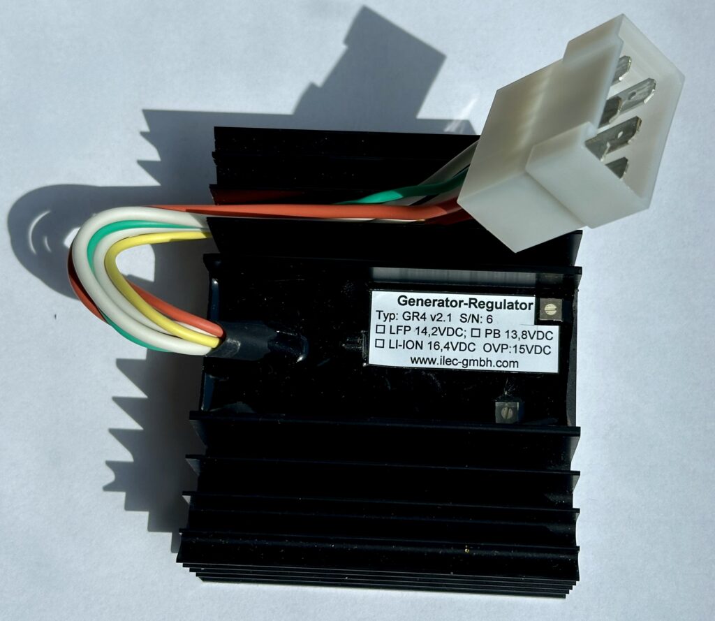
GR4b incl. OVP –
Generator regulator for Rotax, Hirth and Solo engines with lead-acid or LiFePO4 starter battery
Price
€159,66 plus 19% VAT, plus shipping
Technical data of the GR4b generator regulator
| Feature | Specification | Unit |
| Dimensions (L × B × H) | 88 x 75 x 35 | mm |
| Weight | 0,310 | kg |
| Factory set charging voltage | 14,2 | V |
| Adjustable range approximately | ca. 13,7 – 14,8 | V |
| Overvoltage cut‑off | 15 | V |
| Quiescent current consumption (without LED) | ca. 0,5 | mA |
| Discharge current via the yellow OVP lead | ca. 0,1 | mA |
| Minimum operating voltage | ca. 10 | V |
| Output current for the charge control LED | 20 | mA |
| Maximum generator output power | ca. 250 | W |
Operating temperature limits: minimum –20 °C, maximum +70 °C.
Operation only in a dry environment
Functional characteristics
When the main switch is turned on, the charging indicator light comes on first. It goes out as soon as the alternator starts supplying power. The regulator adjusts the system so that the set charging voltage corresponds to the voltage across the thin red cable. Check that this voltage matches the actual battery voltage! If the battery voltage (yellow cable) rises above 15V, charging is interrupted.
Two small potentiometers on the top of the housing allow the charging and overvoltage cut-off voltages to be adjusted to suit the battery system in use, if necessary. Turning them anti-clockwise
increases the charging voltage.
The OVP potentiometer is sealed and must only be adjusted after consulting the manufacturer!
Important safety information for lead and LiFePO4 batteries:
Before installation, check that the charging voltage and overvoltage cut-off voltage are compatible with the battery being used and that the battery is suitable for the maximum alternator charging current!
Unsuitable batteries may overheat and/or be damaged.
Particularly when used with LiFePO4 batteries, approval must be obtained from the UL manufacturer.
Installation of the GR4b charge controller in the aircraft
The regulator is secured with two M5 screws so that the cooling fins are as vertical as possible, in order to achieve optimum cooling. The
installation location should be chosen so that the regulator is not subjected to additional heat from nearby heat sources. The alternator, battery and charge controller are connected via a 6-pin
flat plug, whilst the earth connection is made via the heat sink.
Ensure there is good contact between the regulator housing and the negative terminal of the battery! It is advisable to place a toothed washer between the screw head and the heat sink.
Ensure there is a reliable conductive connection between the regulator housing and the negative terminal of the battery. It is advisable to use a toothed washer between the screw head and the heat sink.